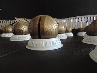
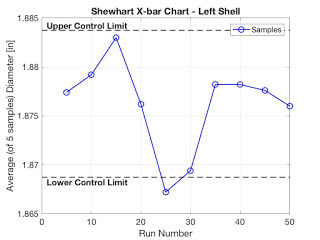
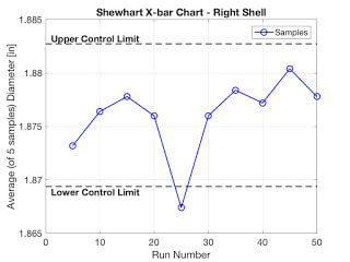
 Figure 1: Fully assembled Yo-Yo Key FeaturesThe Golden Snitch Yoyo comprises of two rings that snap fit into two spherical shells as the main body of the yoyo. Two symmetrical wings press fit into bushings that press fit into the clearance holes in the shells. The entire yoyo sits on a stand that reads “I Open at the Close,” a quote from the Harry Potter series. The fully assembled yoyo can be seen in Figure 1, while each individual component is seen in Figure 2. As seen in the video, the wings appear to flutter while the yoyo is yoyo'd. Multiple yoyos from our production of 50 are visible in Figure 3. SuccessesA design modification was made to the inner rings in order to hold the bushings for the wings in place. Since the clearance hole for the bushings is on a spherical surface, there are no vertical contact points to keep the bushings in place, hence the posts were added. The length and radial position were well placed even accounting for shrinkage to align with the radial position of the clearance hole on the shell. This is visible in Figure 2. The bushings outer and inner diameter of the bushings were also designed and manufactured precisely enough to press into the shells and for the wings to press fit into. The entire yoyo sits at equilibrium in the stand. The ring diameter was also modified to get 0.01" interference fit with the shell of the yoyo to have a tight snap fit. Even though we were not able to meet our goal of having the wings rotate with ball bearings, the wings look like they are fluttering when the yoyo is in action! Opportunities for ImprovementThe assembly process for the yoyo was quite tedious. The bushings had to all be manually reamed for the wings to press fit inside. The shell clearance holes had to align perfectly with the posts on the rings before being snap pressed together which was difficult to do and required re-assembly. Less assembly required for these steps would be better. The weight distribution of the yoyo is uneven because of the wings; overall more weight could be concentrated around the outer diameter of the yoyo for better rotational motion and acceleration. The string gets caught in the wings if not perfectly yoyo’d which is difficult to mitigate in any redesign. Because of the importance of the symmetry in the design of our yoyo and the horizontal alignment of the wings, the set screw could not be tightened all the way into the hex nut. Therefore the sleeve does not lock up against each nut when assembled and the string gap varies. In the short-term, we could fix this by manually adjusting the set screw or sleeve for each yoyo. There was variation in the nut shafts we used for the nut placement so there. For a production version, we should have smaller tolerances on the nut shafts used to place the nuts in the mold. This would tighten the tolerance of the nut cavity and for sleeves and screws of the same/correct size, the yoyos would naturally tighten at the aligned orientation. Shell Production AssemblyDuring production of our Yo-Yo, we tracked the critical dimensions of the shells to see if our production was capable and in-control. The critical dimension for the shells was the ID, so that our rings would have a satisfactory press fit. We previously determined our spec limits for the shell ID to be 1.875" (-0.005"/+0.005"), and plotted these values in a run chart of 100 shells (50 left shells and 50 right shells) shown below in Figure 4 and 5. Figure 8,9: The inner diameter of left and right shell components of the Snitch yo-yo and how they vary over a production run of 100 parts. Parts 21-26 were produced using a cooling time of 10 seconds instead of the default 15 seconds. As seen above, this change had a visible impact on the shell ID, dropping outside of the lower spec limits set. In order to introduce some variation, we lowered the cooling time at run number 25 from 15s to 10s. This disturbance is easily seen in the run charts above, as well as the Shewhart control charts. Given the distribution of samples, control limits were determined and these values were plotted in a Shewhart control chart, with a subgroup size of n = 5, shown below in Figure 2. The control limits were determined according to the formula CL = 𝜇 ± 3𝜎 / √n, where 𝜇 is the average value of all parts, 𝜎 is one standard deviation of all parts, and n is the size of the subgroup. In order to introduce some variation, we lowered the cooling time at run number 25 from 15s to 10s. This disturbance is easily seen in the control charts below. Figure 6,7: The graph above shows the Shewhart X-bar chart for the left and right shells along with the overlaid UCL and LCL values. The blue line above shows the average inner diameter of the shells as a rational subgroup of 5 samples (n=5). As seen in the figure above, this line does not remain within the UCL and the LCL due to the introduction of the disturbance and as a result we can state that this process no longer in control. This was confirmed by calculating the of the process, which turned out to be 0.4472 for both the left and right shells. Since this is less than 1.33, the process is confirmed to be out of control. Table of Specifications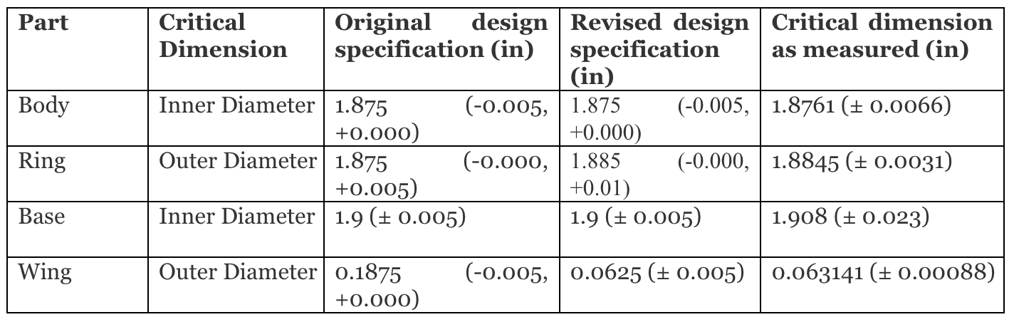 All processes except for the ring were in control, indicating stability in the mean and variation. However, the processes were not fully capable, since parts were not consistently produced within specification. For the body: The average measured inner diameter for the body was outside of the desired specification, and the variation exceeded the value that was originally set. The variations likely occurred due to inconsistencies in the injection molding process. For the ring: The designed specification for the ring changed to account for the measured dimensions for the body. Although some of the parts were outside of the designed specification, assembly proved to be quite successful. For the base: The variation was significantly higher than the originally designed specification. However, since assembly between the yo-yo and the base is relatively flexible, a revised specification would allow for more tolerance. For the wing: The average measured dimension was within the measured tolerance. However, the variation required some adjustments in the final assembly. A revised specification would reflect lower tolerances to enable easy assembly. Cost AnalysisIn order to estimate the total cost to manufacture our 50 prototype yoyo’s and then estimate cost over 50,000, we first needed to identify the sources of cost. Overall, cost comes from 3 categories: Materials, Energy, and Labor. The tables below show how price was broken down. 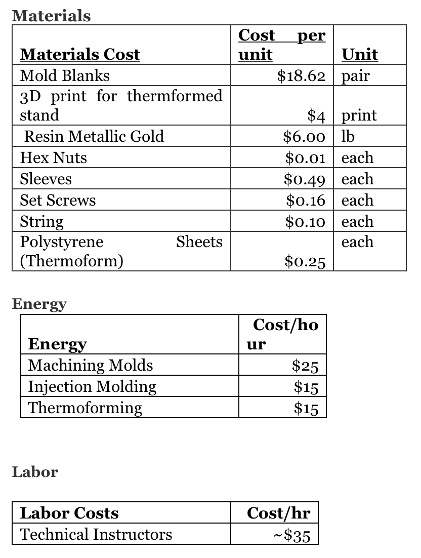 In order to produce 1 yoyo, we need to pay the technical instructors and machine the molds and 3D print. This gives us a fixed cost of $1860.36 before a single yoyo is even made. This does not include general electricity and upkeep since that is independent of the 2.008 class nor production and assembly labor since we technically pay MIT to do this. Once we start manufacturing yoyo’s, we must include cost of materials and machine runtime costs which ultimately causes a $1.49 variable cost increase in total cost per additionally yoyo (see graphs below). To estimate material costs, we assumed 2 hex nuts per yoyo, one sleeve, one set screw, and string and then multiplied the total weight of one yoyo by the per pound cost of metallic gold resin and polystyrene sheets. Machine runtime costs were determined by taking the product of the per hour cost to run the machines by the time it took to produce one part using each machine. Some bigger assumptions that we made that in reality may not be true are that all parts made are in spec (controlled process) and can be used for assembly, all assemblies are made correctly, and that tools, molds, and machines never break/need to replaced. Although these values are not insignificant, we made these assumptions since determining tool life and mold life are longer calculations and assuming all parts works for a prompt that doesn’t ask for cost of “in spec Yo-Yo’s.” 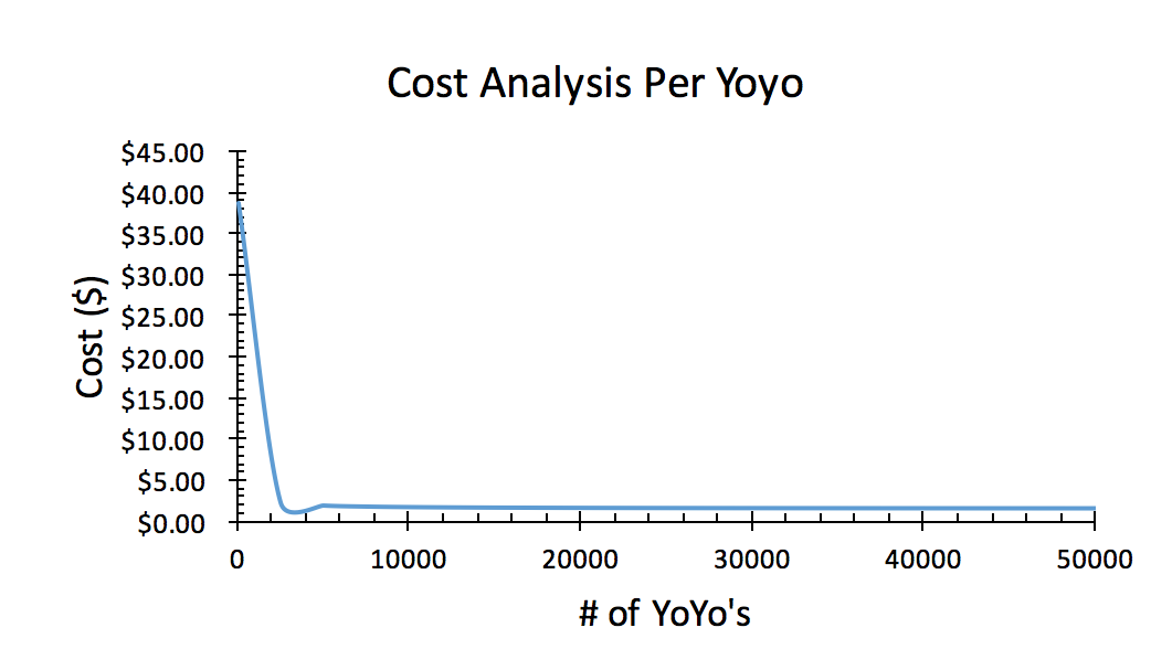 Figure 8: The graph above shows the cost per yoyo over the number of yoyo’s produced. As seen by the steep drop from 50 to 2500 yoyo’s, the sunk costs mentioned above spike the cost per yoyo very high for small productions however as production increases these sunk costs play a smaller role than the material and manufacturing costs. As a result, the cost per yoyo flatlines to ~$1.49/yoyo at 50000 yoyo’s, i.e. the material and manufacturing cost per yoyo. 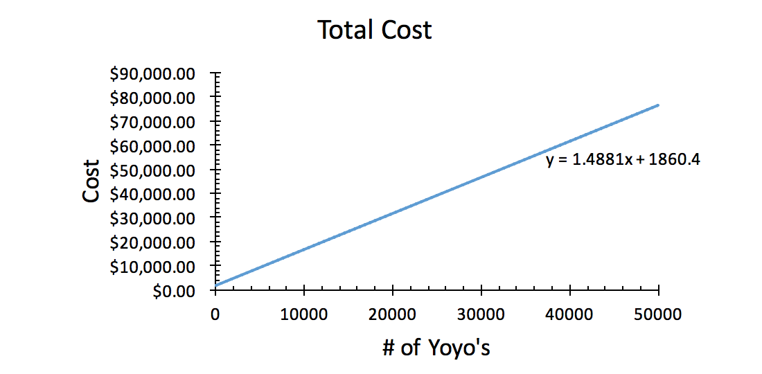 Figure 9: The graph above shows how the total cost of manufacturing changes with the total number of yoyo’s produced. As seen by the linear relationship above, the total cost increases at a rate of `$1.49 per yoyo, which as stated earlier is the total cost of materials and machine runtime for production of one full yoyo without sunk costs. These sunk costs are manifested in the y-intercept of the relationship in the graph above. Manufacturing ConstraintsAfter designing our yoyo, we learned that several of the finer-detailed features we wanted to include were not feasible using the equipment and machines available to us in the 2.008 shop. For example, to give a more realistic ratio between the wings and the shell, we wanted to make our shell 2" OD and then make the wings 4" long. However, the mold sizes we could have used maxed out at a 3.5" x 3.5" square. Additionally, the original wing design had more feathers than our final design does. This is because the smallest tool we could have used was a 1/16" ball endmill. As a result, our wings had to be redesigned even further to accommodate these tool size requirements. Furthermore, our thermoforming mold for the stand had to be 3D printed due to the fact that the shop lacked a 5-axis cnc machine capable to create and machine the letters and various undercuts the stand required. If we were to mass produce these yo-yo's, it would be beneficial to acquire machinery that could efficiently create the molds with the specifications we wanted. For example, have a 5-axis cnc machine to make the thermoforming mold for the stand in order to ensure a longer life for the mold since the 3D printed molds tended to fail after ~30 cycles due to the undercuts in the letters and a weak base material. To account for the detail needed for our yo-yo's, we should buy tools with a wider range of sizes, especially on the smaller end, along with a base stock big enough for our more realistic wing to shell ratio. Assembly wise, we should either design the bearings in such a way that it is easier to snap fit the wings into them, or contain more assembly stations for that step since it is the bottleneck as it currently stands. Thank you for following our journey!
Comments are closed.
|
Six SeekersGroup of six MIT students fabricating a yo-yo that looks like the golden Snitch from Harry Potter. Archives
May 2017
Categories |
 RSS Feed
